A J1939 protocol stack with questionable quality of the source code can have severe consequences for the reliability and safety of heavy-duty vehicles.
The J1939 protocol stack is designed to ensure that various ECUs of a heavy-duty vehicle can communicate with each other efficiently and reliably. If the J1939 protocol stack is not properly tested, it could lead to incorrect or incomplete data being transmitted thus, causing malfunctions or failures of various vehicle components.
For example, let’s imagine an instance when the engine control unit fails to communicate engine speed or oil pressure data to the transmission control module. Obviously, it is the J1939 protocol stack’s fault.
In that case, the transmission may not shift gears correctly which may lead to poor performance or even stalling of the vehicle. Similarly, if the J1939 protocol stack fails to communicate data about brake system performance to the engine control module, it may not be able to adjust the engine’s power output, leading to unsafe driving situations.
Testing the quality of J1939 source code is therefore crucial to ensure the proper functioning of these systems and prevent potential accidents and breakdowns.
Our J1939 software development team has shared a placid walk-through of the basic functions that need to be tested, of each layer of the protocol stack to ensure that you purchase a quality J1939 source code.
For starters, we will introduce J1939 software stack and understand the benefits of integrating pre-tested J1939 software stack solution.
What is J1939 Protocol Software?
J1939 stack is a software solution developed to support seamless communication and diagnostic services within the in-vehicle network (based on CAN bus protocol).
J1939 protocol based software stack is designed for commercial vehicle applications.
J1939 software stack is complaint to Society of Automotive Engineers (SAE) J1939 standard.
This automotive protocol stack has layered software architecture based on seven-layer ISO-OSI model.
The layers required to be configured and integrated while porting the embedded software depend on the requirement of the specific automotive applications.
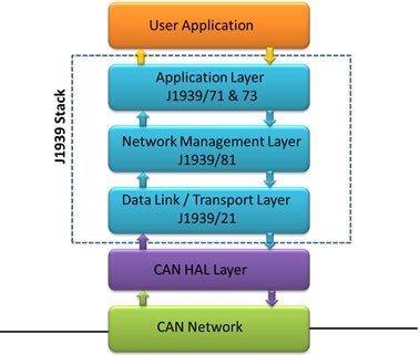
The consistent layers of the J1939 software stack, available as off-the-shelf solution include: Data link layer, Network management layer and application layer.
Represented in the figure below, is the architecture of J1939 software stack:

Source: /blog/embedded-blog/what-is-j1939-software-stack
What are the benefits of integrating a verified and validated J1939 software stack?
J1939 stack is readily available as an off-the-shelf solution. A number of automotive engineering services and tool vendors have launched their pre-packaged and pre-tested SAE J1939 solution.
Integration of such re-usable J1939 software solution with automotive and tooling applications ensures significant savings in development time and cost.
Purchasing an off-the-shelf SAE J1939 protocol stack is a cost-effective option in scenarios similar to the following:
- As an automotive OEM or Supplier, your R&D team wants to focus on core product development activities.
- Your in-house R&D or embedded software development team do not have expertise in protocol stack design and development.
- Your team is facing certain road-block during product development and there are time and cost constraints.
Partnering with a renowned embedded software development vendor also has an added advantage of testing, support and maintenance services that are part of the engagement.
Now that you have arrived at the decision of outsourcing or purchasing pre-tested SAE J1939 stack solution, it is important that you invest in good quality software.
A pre-tested and pre-packaged J1939 software solution ensures you a re-usable stack, thus setting a benchmark among the variety of other automotive software services vendors.
Validating or testing the layered architecture design of J1939 stack
As already mentioned, J1939 software stack typically consists of the following layers:
- Data Link / Transport Layer (J1939/21)
- Network Management Layer (J1939/81)
- Vehicle Application Layer (J1939/71 & 73)
Here are some of the specific basic functions that need to be checked in each of these layers.
Data Link / Transport Layer:
- Peer to Peer communication
- Broadcast Announce Message
Network Management Layer:
- Address Claim Message
- Self – Configurable Address
- Commanded Message
Vehicle Application Layer:
- Tx and Rx of Standard SPNs packed in PGN’s.
How to check the basic functions of different layers of J1939 solution?
To test the specific functions of each layer, one can design certain test cases.
The derived outcomes indicate if the concerned layer has been designed as per the desired quality or not.
Checking for the aforementioned functionalities ensures an efficient and cost-effective J1939 stack.
J1939/21 – DataLink / Transport Layer:
- Peer to Peer Transport Protocol: Peer to peer TP is a dedicated protocol in which the source and destination is following a one-to-one (among ECUs) data transmission.
- Broadcast Announce Message(BAM) : BAM is the acronym used for Broadcast Announce Message, generally used for transmission of data greater than 8 bytes.
The BAM is a protocol that follows the one-to-many pattern of communication among the ECUs.
Both the peer to peer and BAM has a particular sequence and structure as defined by the SAE standard. We can validate the structure and functionality using case scenarios and demo PGNs.
For example:
We can check for transport Broadcast Announce Message using CAN tool, by checking if the ECU (electronic control unit) under test, is transmitting BAM Message with 8 bytes of data message.
These 8 bytes should encompass the first message as sequence number and remaining 7 bytes are data.
Also unused data bytes of last transport data packet should be filled with 0xFF, according to ideal scenario.
J1939/81 -Network Management layer:
- Address claim: Each device connecting to the network sends an immediate acknowledgement in form on address claim message.Now, there can be conflicts in the addresses (duplicity) of the devices that send the address claim messages to the network.This situation can be mitigated by two logical manipulations:
- Self-configurable address: The algorithm should affirm the ECU’s ability to randomly pick its own address in case of conflict. The priority of the devices should be taken into consideration while address claiming during integration of the stack with application.
- Commanded Message: This again is an algorithm specified message which claims the address according to the input command.
While testing for the above functionality we make sure, the PGN to be tested satisfy the criteria of the test case.
For example:
To check address claim message, a CAN tool can be used. The ECU under test which is being ported with J1939 software stack, should send the first message as an address claim message to claim the address on the network.
Similarly test cases can be checked for self-configurable and commanded message functionalities.
J1939/71 & 73- Vehicle Application Layer
Vehicle Application Layer of J1939 protocol stack manages transmitting and receiving of PGNs’ (Parameter Group Number) messages within the in-vehicle CAN network.
Each PGN consists of various SPNs’ (Suspect Parameter Number) which are nothing but vehicle parameter data fetched from the CAN network.
Such data (SPNs’) are received and transmitted by automotive ECUs’ (control units) through Vehicle Application Layer.
The J1939/71 & 73 protocol standard has a defined unique SPN for each vehicle parameter.
For example – For engine RPM there is a pre-defined unique SPN mentioned in J1939/7x documents.
For testing the source code of J1939 stack designed by an embedded services vendor, one needs to check if control units within the network are able to accurately transmit and receive the data parameters stored in SPNs’
Let’s take an example of SPN 177, which represents Transmission Oil Temperature in PGN 65272.
It consists of two bytes of data. The value of Transmission Oil Temperature ranges from -273 to 1735 degree centigrade with offset of 0.03125 deg C / bit.
With the help of a CAN Tool one can monitor the Tx& Rx of this SPN in PGN 65272 over a CAN Bus network
Change the values from minimum to medium range and to maximum range and check if it is being transmitted correctly between the ECUs’ over CAN network.
Let’s try to understand the kind of deficiency the J1939 source code can have in terms of functionality, error handling, message format and so on.
Here’s a J1939 source code snippet that has certain flaws:
void j1939_send_message(uint32_t id, uint8_t* data, uint8_t length)
{
uint8_t tx_buffer[8];
tx_buffer[0] = id >> 24;
tx_buffer[1] = id >> 16;
tx_buffer[2] = id >> 8;
tx_buffer[3] = id;
for(uint8_t i = 0; i < length; i++)
{
tx_buffer[i + 4] = data[i];
}
CAN_SendMessage(tx_buffer, 8);
}
This code has several issues:
- The code does not use the correct format for J1939 messages.
- There is no error handling mechanism defined in the code.
- The code is not modular and is tied to CAN Bus interface.
An improved version of code could be:
typedef struct {
uint8_t source_address;
uint8_t destination_address;
uint8_t priority;
uint32_t pgn;
uint8_t data[8];
} j1939_message_t;
int j1939_send_message(j1939_message_t* message) {
// Validate input parameters
if(message == NULL) {
return -1;
}
// Convert message to CAN format
uint8_t can_data[8];
can_data[0] = message->pgn & 0xFF;
can_data[1] = (message->pgn >> 8) & 0xFF;
can_data[2] = message->priority;
can_data[3] = message->destination_address;
can_data[4] = message->source_address;
memcpy(&can_data[5], message->data, 3);
// Send message on CAN bus
CAN_SendMessage(can_data, 8);
return 0;
}
// Main function
int main() {
// Initialize the J1939 network
// …
// Send a J1939 message
j1939_message_t msg;
msg.source_address = 0x01;
msg.destination_address = 0x02;
msg.priority = 0x06;
msg.pgn = 0xEF00;
msg.data[0] = 0x01;
msg.data[1] = 0x02;
msg.data[2] = 0x03;
j1939_send_message(&msg);
// Receive and process J1939 messages
while(1) {
// Code to receive and process J1939 messages
}
}
The issues with the previous code snippet has been addressed in the blog.
- J1939 message structure is used.
- Input parameters have been validated and J1939 messages converted to correct CAN format.
- The code is more modular and can be easily reused in other projects.

The pre-tested layers of J1939 source code as informed in the testing guide above, will help you to make more informed decision before outsourcing the software development project.

